 CompanyGraph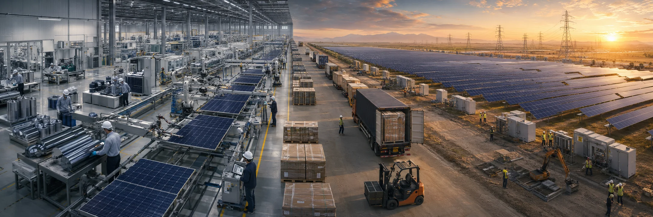
Follow a solar module from refined material to decades outdoors, and see how manufactured panels become usable electricity.
From quartz and glass to a wired array
Most solar panels begin with crystalline silicon. Quartz is reduced to metallurgical-grade silicon, then purified into polysilicon. Producers melt the polysilicon, grow a single-crystal ingot, slice it into thin wafers, and texture, treat, coat, and add metal contacts to each wafer until it becomes a photovoltaic cell. Cell makers test and sort the cells. Module factories connect them electrically, seal them between protective layers—usually including glass and polymers—and add a frame, junction box, cables, and connectors.
That is the main route, not the only one. Thin-film modules deposit a light-absorbing semiconductor onto glass or another substrate and avoid the ingot-and-wafer path. Both routes also depend on materials and equipment that a silicon-only account misses: glass, aluminium, copper, silver or other conductors, plastics, process chemicals, furnaces, factory electricity, water, manufacturing tools, and human work.
A finished module then travels to a roof, car park, field, or other exposed surface. Installers secure it to a structure, connect modules into an array, add protective electrical equipment and monitoring, and connect the direct-current output to an inverter. The inverter supplies alternating current to a local load, a battery, or the electricity network. Unlike coal or gas, sunlight is not shipped to the generator. The conversion equipment is moved to the resource, fixed in place, and expected to work through weather for decades.
A panel converts light only through a connected electrical circuit
When light reaches a photovoltaic cell, some photons are reflected or pass through and some are absorbed. Absorbed energy can free charged particles in the semiconductor. The cell’s internal structure directs those charges, and metal contacts collect their movement as electric current. The US Department of Energy’s cell explanation describes this conversion without suggesting that all incident light becomes electricity.
The installation needs electricity services, not a panel count. Module demand follows added load, replacement, storage, orientation, shading, conversion losses, degradation, and the ability of the grid to use output when it is produced.
Some module volume is physically required by sunlight and conversion limits; some reflects the present arrangement of sites, equipment, finance, and networks. Those conditions can enlarge demand without making one exact module volume inevitable.
Purity is one branch of the material story
Silicon is abundant in the earth’s crust, but a solar cell cannot use quartz directly. Oxygen and other elements must be removed, and the silicon must be purified enough that unwanted impurities do not overwhelm the cell’s intended electrical behavior. The purified material is melted into a controlled crystal and sliced. Sawing creates silicon kerf—the material removed by the wire—and cell processing uses heat, chemicals, coatings, and metallisation to form the light-responsive device. The DOE manufacturing guide follows these transformations and also shows the separate thin-film route.
Solar-grade purity should not be treated as identical to the material specification for an advanced logic chip. Both products require carefully controlled semiconductor material, but their acceptable impurities, crystal requirements, device structures, manufacturing processes, and final functions differ. Nor does purification alone determine supply. A module cannot be assembled without suitable glass, encapsulating material that bonds and protects the cells, electrical conductors, a junction box, connectors, and often an aluminium frame.
Each input has its own transformation and loss. Glass and aluminium require heat; silver and copper begin in mining and refining; polymers begin in chemical supply chains; cell and module factories consume electricity and materials while rejecting off-specification output. A lower module price records a payment under particular terms. It does not by itself establish that less material or energy was consumed, that manufacturing electricity had lower emissions, that workers faced the same conditions, or that the module will deliver more electricity over its life.
Material requirements also change with design. Thinner wafers reduce silicon per module but may be harder to handle without breakage. Reducing silver use can ease demand for one material while requiring a different contact design. Removing a frame changes aluminium demand and affects mounting and handling. Higher cell efficiency can produce more rated power from the same area, yet lifetime energy still depends on degradation, climate, layout, and system operation. “Less material per watt” is a defined manufacturing measure, not a complete result.
Every cell joins a shared current path
A cell produces little power by itself, so factories connect many cells into a module and installers connect modules into strings and arrays. Series connection raises voltage, but it also joins the devices electrically: within a series string, the same current must pass through each element. Small manufacturing differences, unequal temperature, dirt, shade, cracks, or degradation can give the connected cells or modules different preferred operating points.
The array cannot operate every series-connected device independently. It settles on a combined operating condition, so mismatch can reduce output even when most cells are undamaged. The Sandia PV Performance Modeling Collaborative explains how series strings share current and parallel strings share voltage at their common connection. Bypass diodes can route current around groups of limited cells, and power electronics can isolate parts of an array, but these controls change the consequence; they do not remove the physical mismatch.
Module assembly is therefore more than putting a cover around cells. Factories sort cells, make and inspect electrical joints, lay the circuit between protective materials, laminate it, attach the junction box, and test the completed current-voltage response. Encapsulation must transmit light while resisting moisture, ultraviolet radiation, heat, mechanical load, and thermal movement. A connection that is satisfactory at the factory must remain conductive after thousands of outdoor temperature cycles.
The label sees a controlled sun
A module’s nameplate power is a reference measurement. Standard test conditions hold irradiance at 1,000 watts per square metre, cell temperature at 25°C, and the light spectrum to a defined reference. Those conditions let laboratories and factories compare modules on a common basis. They do not reproduce a year outdoors. An NREL performance report notes that field irradiance is usually below the reference level and operating cells are commonly hotter.
Real output changes with the sunlight reaching the module, its angle and spectrum, cell temperature, shade, dirt, snow, wind, and the condition of the electrical system. Heat is especially easy to misunderstand: bright sun can raise cell temperature, and higher temperature generally reduces a silicon module’s voltage even while sunlight is abundant. The mounting arrangement changes cooling, so two copies of the same module can operate differently.
Several quantities that all use watts or watt-hours answer different questions:
- Nameplate DC power describes the module under the rating conditions.
- Installed DC capacity adds the nameplate ratings of modules present at a site; it does not show whether they are illuminated or operating.
- Operating AC power is the instantaneous output after the array, wiring, and inverter have acted under current conditions.
- Metered energy accumulates output over time at the meter’s location; energy behind that point may have been used, stored, limited, or lost differently.
A factory flash test, a type-qualification certificate, commissioning data, an inverter log, and a revenue meter therefore observe different objects. Qualification exposes selected module samples to defined electrical, mechanical, and environmental stresses. It is essential screening, but it is not a direct observation of every manufactured unit or a guarantee of a particular life in every climate. DOE’s work on PV reliability and safety exists partly because accelerated tests still have to be connected to real failure modes and service conditions.
Installation completes the conversion system
A module at a warehouse is manufactured supply, not an operating solar system. The intended site needs adequate area, sunlight, structural support, access, and a viable route for the electricity. Racking or trackers hold the modules against wind and other loads. Cables, connectors, switches, grounding, fuses, and protective devices form the DC path. An inverter finds an operating voltage and current and converts direct current into the alternating current used by most grids and buildings. DOE’s inverter guide also explains why the inverter must match grid voltage and frequency and may help control the system’s interaction with the network.
For a rooftop project, available actions depend on roof condition, structural and electrical work, safe access, local approval, an installer’s time, and interconnection rules. For a large project, land access, civil works, substations, transmission or distribution capacity, environmental review, equipment delivery, and trained construction work may be decisive. These functions cannot be replaced by producing another module.
Money must also arrive before electricity does. Manufacturers finance materials and production; distributors hold inventory; project developers secure sites and approvals; installers buy equipment and pay workers; owners or lenders fund construction while a project is not yet generating. A lower panel price makes one action easier, but total installed expenditure also includes inverters, structural and electrical equipment, field work, engineering, permitting, interconnection, overhead, and sometimes storage. NREL’s 2024 solar cost benchmark keeps those categories separate because their relative importance changes by residential, commercial, and utility-scale system.
At the final boundary, the load or grid must accept the electricity. An inverter may reduce output to protect equipment, maintain local voltage, follow an operator’s instruction, or respect an export limit. A battery can move some energy to another time, but adds its own power, capacity, state-of-charge, conversion, and lifetime limits. Installing more panels can increase potential generation without removing the constraint that prevents output from leaving the site.
Abundant modules can wait behind another constraint
“Solar capacity” may refer to polysilicon output, wafer production, cell lines, module assembly, modules in storage, installed DC ratings, or grid-connected AC power. These are not substitutes. A region can assemble modules while importing its cells. A large module factory cannot make wafers with the same equipment. A warehouse surplus does not provide an inverter, transformer, qualified installer, suitable roof, project finance, or interconnection.
Manufacturing is also concentrated by stage rather than by one universal solar market. The International Energy Agency estimated in its 2026 technology assessment that China held around 85 percent of solar supply-chain production capacity and about 95 percent of photovoltaic wafer capacity. Those are dated observations of present industrial organization, not physical laws. They also show why “panel origin” can be too coarse: quartz, polysilicon, wafers, cells, glass, frames, module assembly, inverters, and installation may have different origins and concentrations.
Moving one stage does not recreate the others. Module assembly can expand without a local wafer or cell route. Building upstream capacity requires equipment, process knowledge, energy, inputs, customers, working money, and enough time to reach the required output. Conversely, global module production can exceed installations when project development, networks, money, or local work cannot absorb it. The important shortage is the missing compatible function, not the broadest product category.
Compatibility also matters after installation. A replacement module must fit the available space and mounting, operate within the string and inverter’s voltage and current limits, connect safely, and satisfy applicable approvals. A newer module with a better nameplate rating may not be a direct substitute. Keeping spares consumes storage and money; relying on future purchases may fail when dimensions, connectors, ratings, or product lines change.
The weather tests the complete stack
Once installed, a module encounters ultraviolet light, humidity, heat, cold, wind, hail, salt, dust, mechanical loading, and repeated expansion and contraction. Glass can break, cells can crack, polymers can discolour or separate, moisture can enter, conductors can corrode, and electrical joints can gain resistance. Output can also decline gradually without a single visible break. Module design decides which stresses reach the cell, while site design and maintenance decide how loads, drainage, ventilation, vegetation, dirt, and damage are managed.
The panel is only one part exposed to failure. In a study of annual production and maintenance records from 100,000 systems, NREL researchers found reported module failures were relatively rare, while inverters were the component reported to fail most often; installation-related connector, wiring, breaker, and fuse problems also affected performance and safety. That 2020 study describes one large dataset, not every climate or product, but it demonstrates why module quality cannot stand in for system reliability.
A falling meter reading does not identify the cause. Weather variation, growing shade, soiling, inverter downtime, a tripped protective device, wiring loss, sensor error, curtailment, and module degradation can produce similar observations. Diagnosis requires comparison with the available solar resource and temperature, then inspection at the array, string, module, and component levels. Early detection matters only if someone can reach the site, isolate the cause, obtain a compatible part, and has authority and money to correct it.
Warranty documents, serial numbers, factory test results, installation drawings, inverter logs, maintenance records, and meter data support different parts of that work. If the owner, installer, operator, manufacturer, and network company hold separate fragments, a recorded loss may remain easier to allocate contractually than to correct physically. Dependable supply requires the field observation to reach the participant able to change the relevant design, process, installation, or operating condition.
A module may leave service before it stops working
End of service is not one physical state. A module may be destroyed by weather, become electrically unsafe, fall below the output required by its site, lose compatibility with other equipment, or be removed when an owner repowers the site with newer modules. In the last case, the module can retain useful output even though it no longer fits the original project’s land, contract, labour, or revenue arrangement.
Reuse requires safe removal, transport, inspection, electrical testing, a suitable new site, and confidence in remaining life. Repair may be possible for some cables, junction boxes, frames, or backsheets, while broken cells and laminated internal connections are difficult to reach without damaging the module. Recycling can recover bulk glass and aluminium and potentially copper, silicon, silver, or semiconductor material, but separating bonded layers and producing sufficiently pure outputs requires equipment, energy, work, and an outlet for the recovered material.
The US Department of Energy’s end-of-life review distinguishes continued operation, repair, reuse, repowering, recycling, and disposal. It also reports that, under current US conditions, recycling generally costs more than landfill disposal. That money comparison helps explain the available action; it does not mean disposal preserves more material or causes less damage. Collection infrastructure, responsibility, regulation, transport distance, module design, and recovered-material specifications determine whether a physical return path exists.
Inside CompanyGraph
Explore the material suppliers, wafer and cell producers, module manufacturers, inverter and equipment providers, installers, project owners, utilities, and recovery relationships that connect solar materials to usable electricity inside CompanyGraph.